

Proper CNC clamping is not about tightening harder—it is about controlling where cutting forces go, how the part closes onto its supports, and how safely the load reaches the T-slots without damaging the cast-iron machine table.
Across Indian CNC and VMC job shops, poor clamping remains one of the biggest hidden causes of tool breakage, dimensional errors, table damage, and unsafe machining conditions. Understanding the fundamentals of clamping helps operators improve accuracy, extend tool life, and protect expensive machines.
Basic CNC Clamping Principles
At operator level, three fundamentals decide whether a setup succeeds or fails:
- The workpiece must sit on a rigid, clean datum
- Clamps must push the part into that datum
- The load path must be short and direct into the machine table
Any burrs, chips, rust, paint, or oil trapped between the job, parallels, or vice jaws behave like spring pads. Under cutting forces, the part settles, rocks, or shifts—causing size variation the moment roughing begins.
For milling operations, clamping must resist forces in X, Y, and Z directions, not just hold the part down. A reliable setup always combines:
- Location: fixed jaw, stops, dowels, reference edges
- Clamping: movable jaw, strap clamps, studs and T-nuts
How Cutting Forces Act on a Clamped Workpiece
Milling Forces
Each flute entering a milling cut generates tangential force that pushes the job in the feed direction and can lift or tilt it depending on cutter rotation.
In modern CNC machining, climb milling is common. Here, the cutter tends to pull the part into the cut. If clamping along the feed direction is weak, the job creeps, slips suddenly, or leaves step marks—often followed by tool breakage.
Drilling Forces
Drilling creates mainly axial force. As the drill breaks through, it tries to lift the part—especially thin plates and angle brackets.
- Bending thin plates
- Oversize or tapered holes
- Dangerous job spinning if the part comes loose
Typical Indian VMC Workholding Practices
Most Indian job shops running BFW, Ace, Jyoti, LMW, and Haas India machines rely on:
- Standard machine vices (160–175 mm)
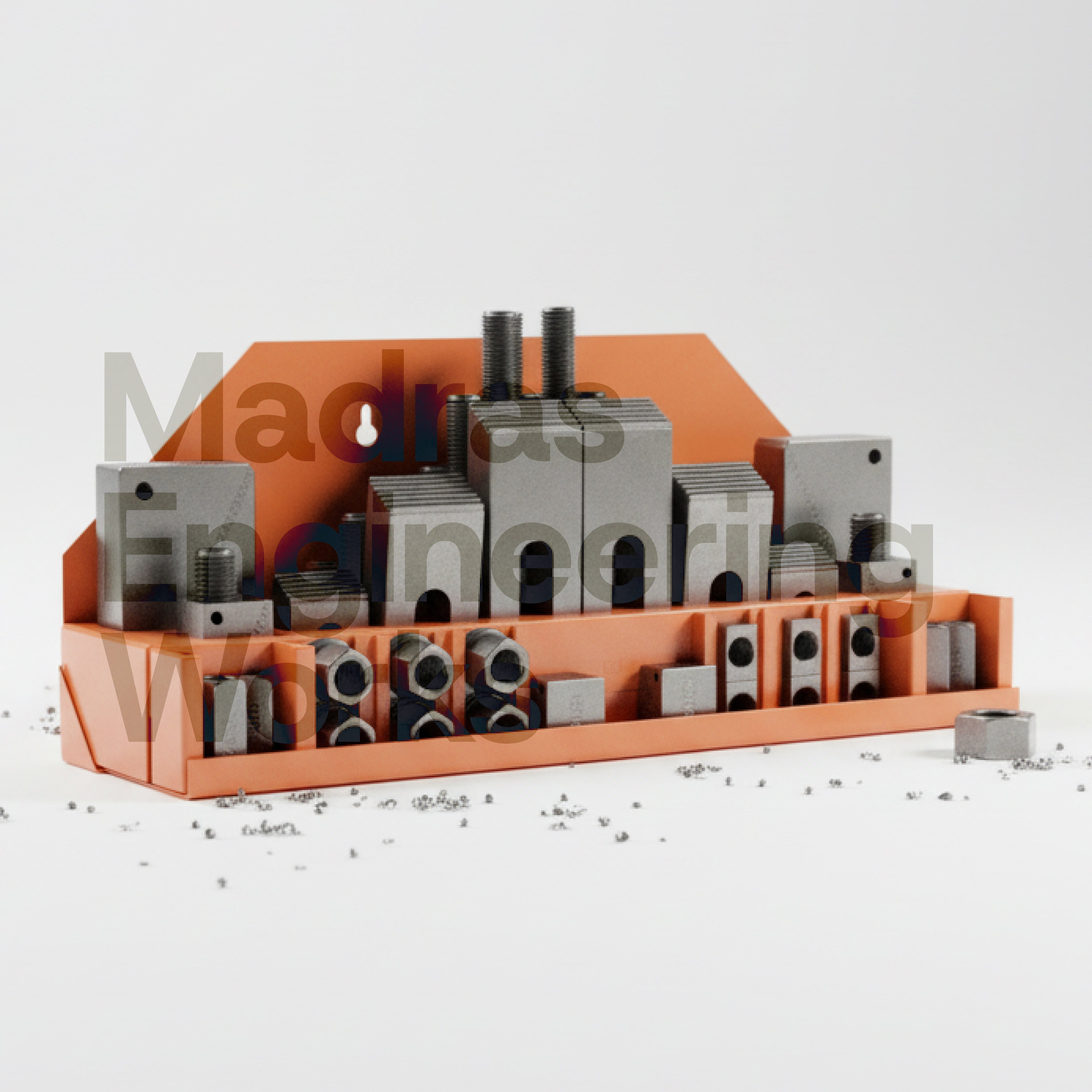
- Strap clamps with studs and T-nuts
- Occasional angle plates or custom plates
A common layout includes one central vice with parallels, a rough stopper plate, and additional jobs clamped directly to the table wherever space is available.
In many smaller shops, the same bent clamps, mushroomed studs, and unknown-grade T-nuts are reused across machines. In such cases, the weakest element—not the machine—decides the real safe clamping force.
Common CNC Clamping Mistakes in Job Shops
- Clamping on scale, rust, or paint without stoning contact surfaces
- Using tall parallels and clamping high on vice jaws
- Overhanging parts clamped only on one end
- One-sided clamping without opposite support
- Mixing soft, low-grade hardware with high tightening torque
These mistakes convert cutting forces into bending moments, vibration, and sudden part movement—often discovered only after scrap or damage occurs.
Theory vs Indian Shop Floor Reality
Textbooks assume ideal rectangular parts, clean vices, calculated forces, and torque-controlled tightening.
In reality, Indian job shops deal with flame-cut plates, warped castings, weldments, and urgent delivery timelines. Operators often rely on experience and instinct—adjusting setups only after something moves or breaks.
Fixtures are frequently built around drawings instead of real part distortion, leading to excessive shimming and packing that defeats original clamping theory.
Why CNC Machine Tables Get Damaged
CNC VMC tables are typically made of grey cast iron. They are strong in compression but weak in tension and shock.
When clamps are set at steep angles with tall stacks of studs and packing, clamping force creates a bending moment on T-slot lips instead of pure compression into the rib.
- Over-length studs bearing on slot chamfers
- Heavy hogging near table edges
- Hammer-tightening under load
OEM and Toolroom Best Practices
- Use hardened T-nuts and correctly sized studs
- Ensure full thread engagement below the slot surface
- Keep clamps level using step blocks
- Use quality vices with correct jaw height
- Protect the machine table with sub-plates when possible
Impact on Safety, Accuracy, and Cost
Improper clamping is a major cause of flying workpieces, tool breakage, spindle damage, and operator injury.
Even small job movement during roughing leads to taper, rework, delivery delays, and customer rejection. One damaged table or scrapped casting can cost more than upgrading the entire clamping setup.
Real-World Failure Scenarios
- Plate jobs lifting mid-cut and spinning during climb milling
- Heavy castings cracking both the part and T-slot lips
- Thin aluminium housings springing open after unclamping
- Worn vices causing jaw lift and out-of-square machining
Conclusion
Proper CNC clamping is not about force—it is about control. When load paths are short, supports are solid, and hardware is correct, machining becomes safer, faster, and more predictable.
Good CNC clamping is invisible when done right — parts stay stable, tools last longer, and machine tables remain damage-free for years.
If you want clarity on choosing the right T-bolts, studs, T-nuts, step blocks, or clamps for your CNC or VMC machine, Madras Engineering Works is always happy to help.


0 comments