
How to Clamp Irregular Parts for CNC Machining — A Practical Guide for Indian Workshops
Castings, forgings, weldments, and complex machined blanks are the components that cause the most setup time in Indian VMC shops. Standard strap clamp and step block setups assume a flat, accessible workpiece. Irregular parts have none of these properties: rough datum surfaces, raised bosses that block straight clamp access, recesses that make clamping points inaccessible, and geometry that makes a standard setup impossible.
This guide covers the step-by-step approach used by experienced fixture engineers. It assumes a standard VMC with T-slot table — the setup equipment used in the vast majority of Indian tool rooms.
Step 1: Identify the Primary Datum Surface
Before selecting any clamping components, identify the primary datum surface — the reference from which all the machined dimensions will be located. This is usually the largest flat or semi-flat face on the workpiece.
For a casting: the datum surface is usually the parting line face or a machined pad on the casting. For a weldment: usually the most precisely prepared face. For a complex aluminium extrusion: often the back face.
The primary datum must contact the machine table (directly or through support elements) at exactly three points — the 3-2-1 locating principle.
Step 2: Apply the 3-2-1 Locating Principle
| Contact Points | Plane Constrained | Degrees of Freedom Removed |
|---|---|---|
| 3 primary points (datum plane) | Primary | 3 (Z translation + 2 rotations) |
| 2 secondary points (datum edge) | Secondary | 2 (X translation + 1 rotation) |
| 1 tertiary point (datum end) | Tertiary | 1 (Y translation) |
The three primary points should form as large a triangle as possible on the datum surface — the wider the triangle, the more stable the workpiece against tipping under cutting force. If the three points are clustered together, a small cutting force moment can tip the workpiece about the cluster.
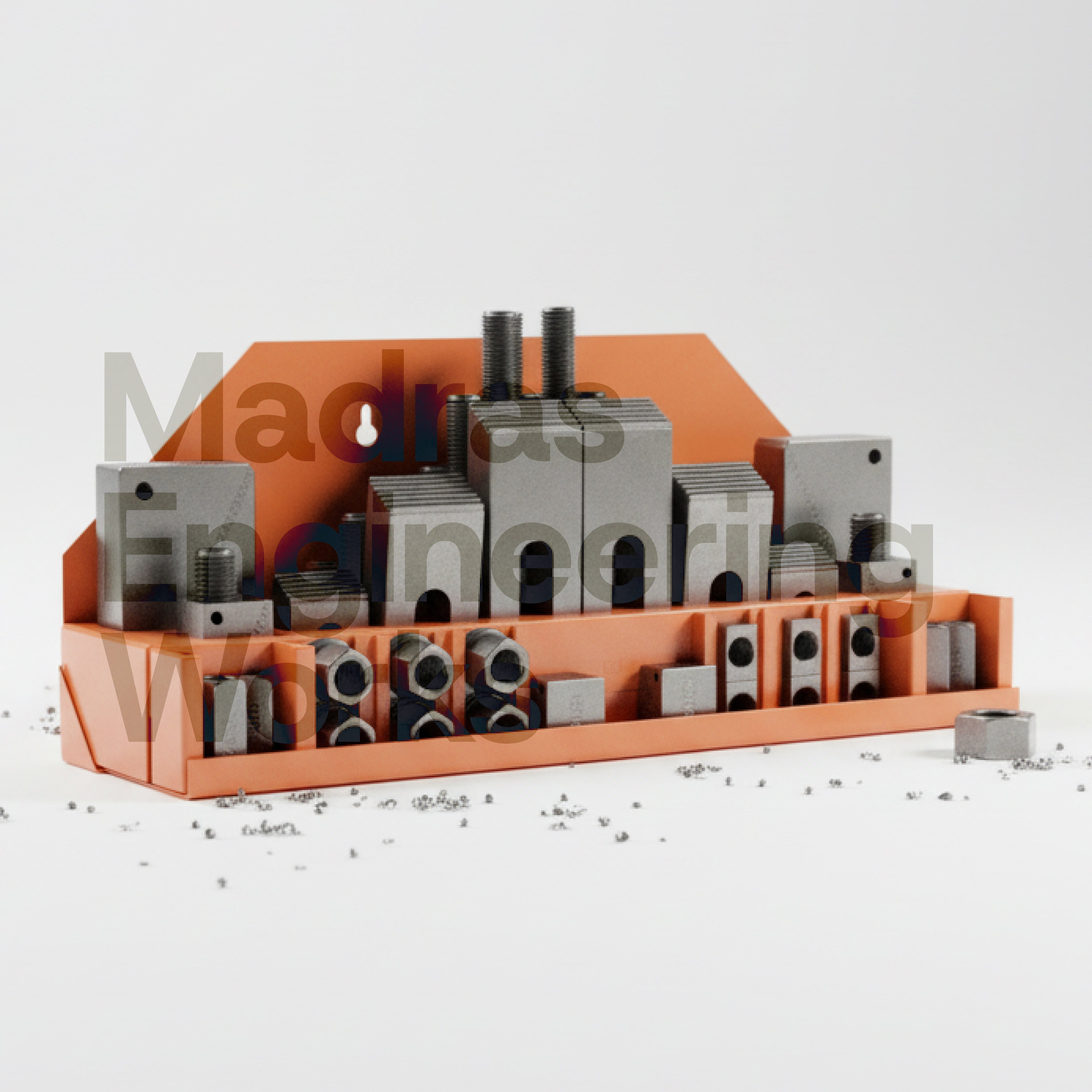
Step 3: Select Workpiece Support Elements for Irregular Surfaces
Standard step blocks assume a flat datum surface. Most castings and forgings do not have flat datum surfaces. Use the correct support element for each situation:
| Datum Surface Condition | Correct Support | MEW SKU |
|---|---|---|
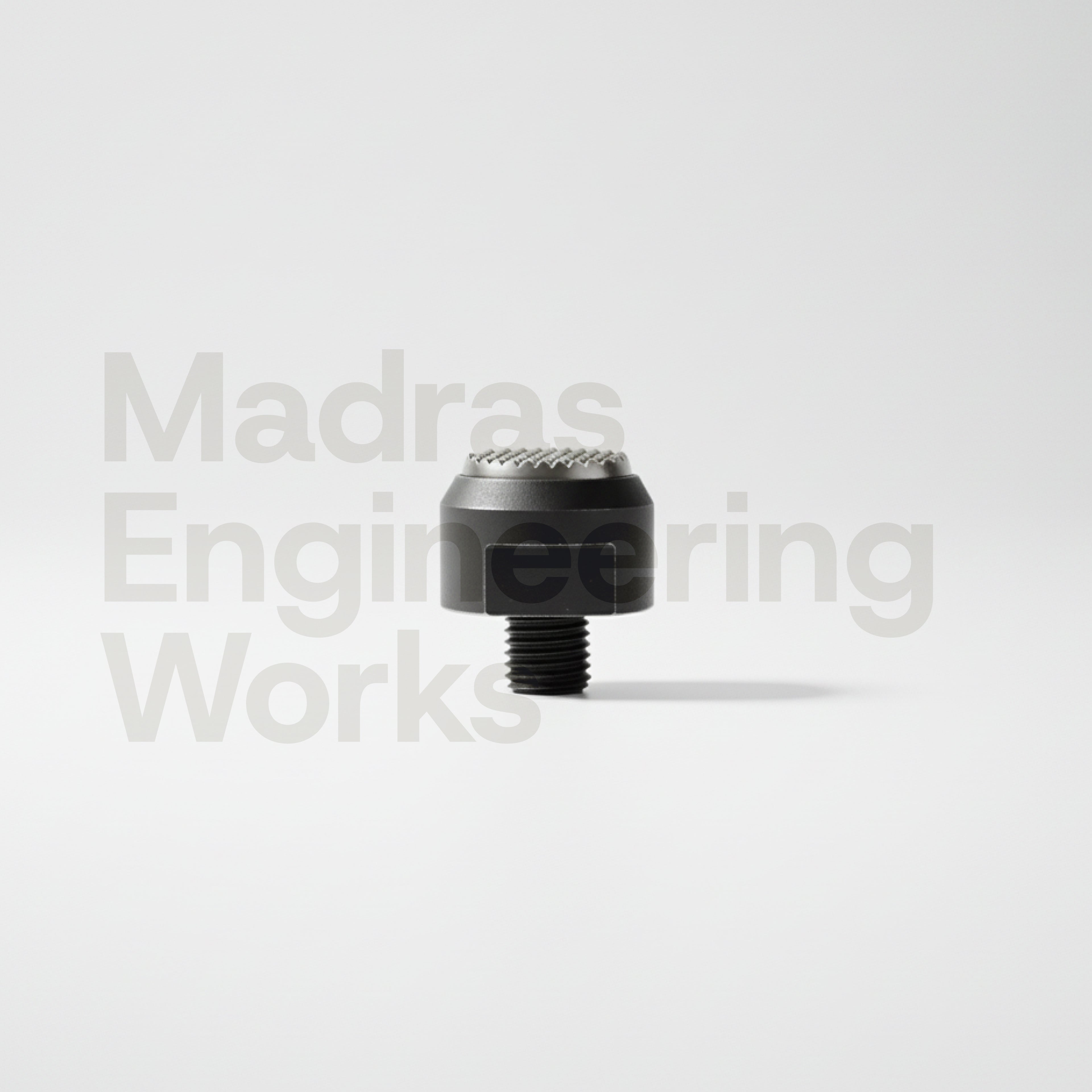
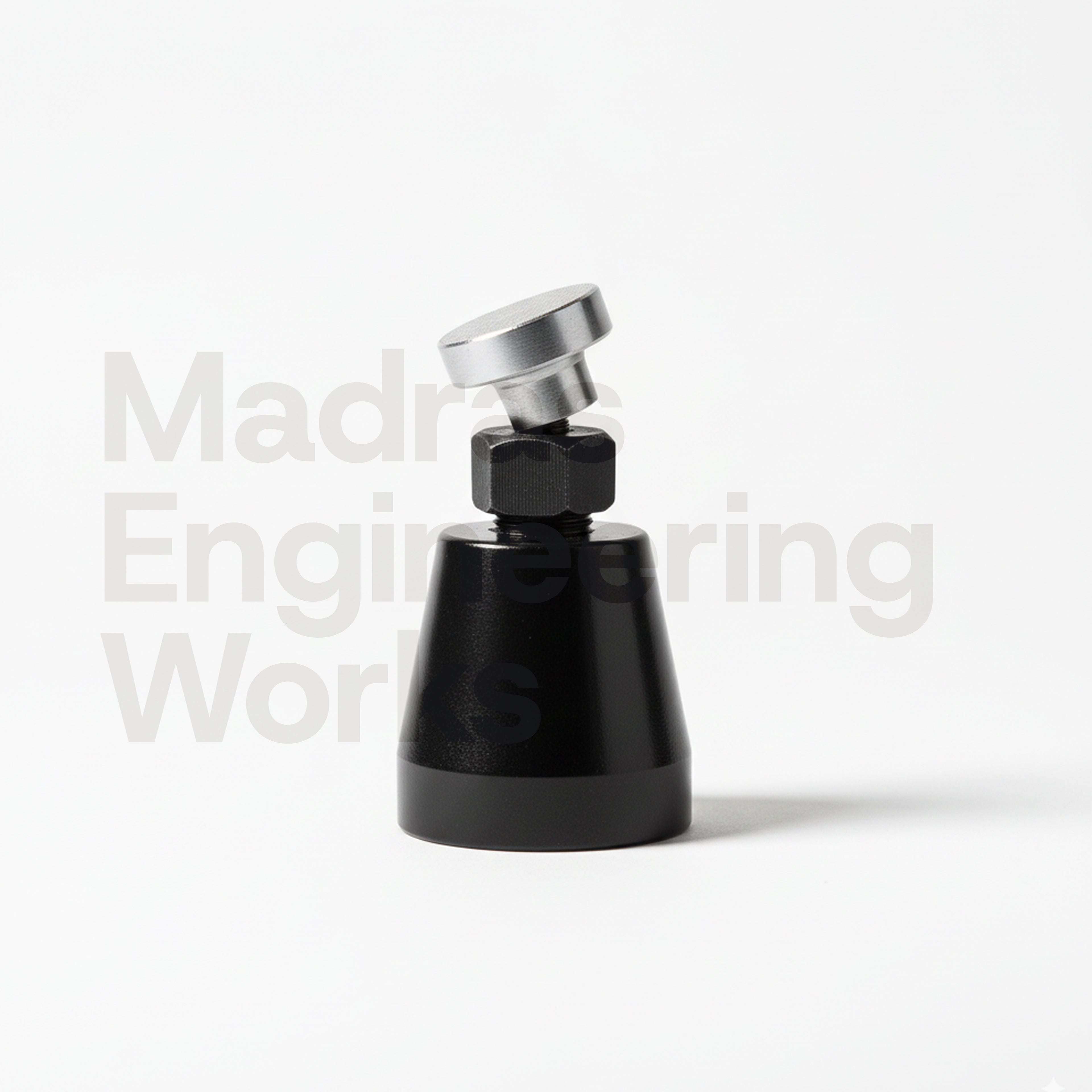
| Rough casting surface, angled | Swivel-Head Screw Jack | CES-STSB-45 |
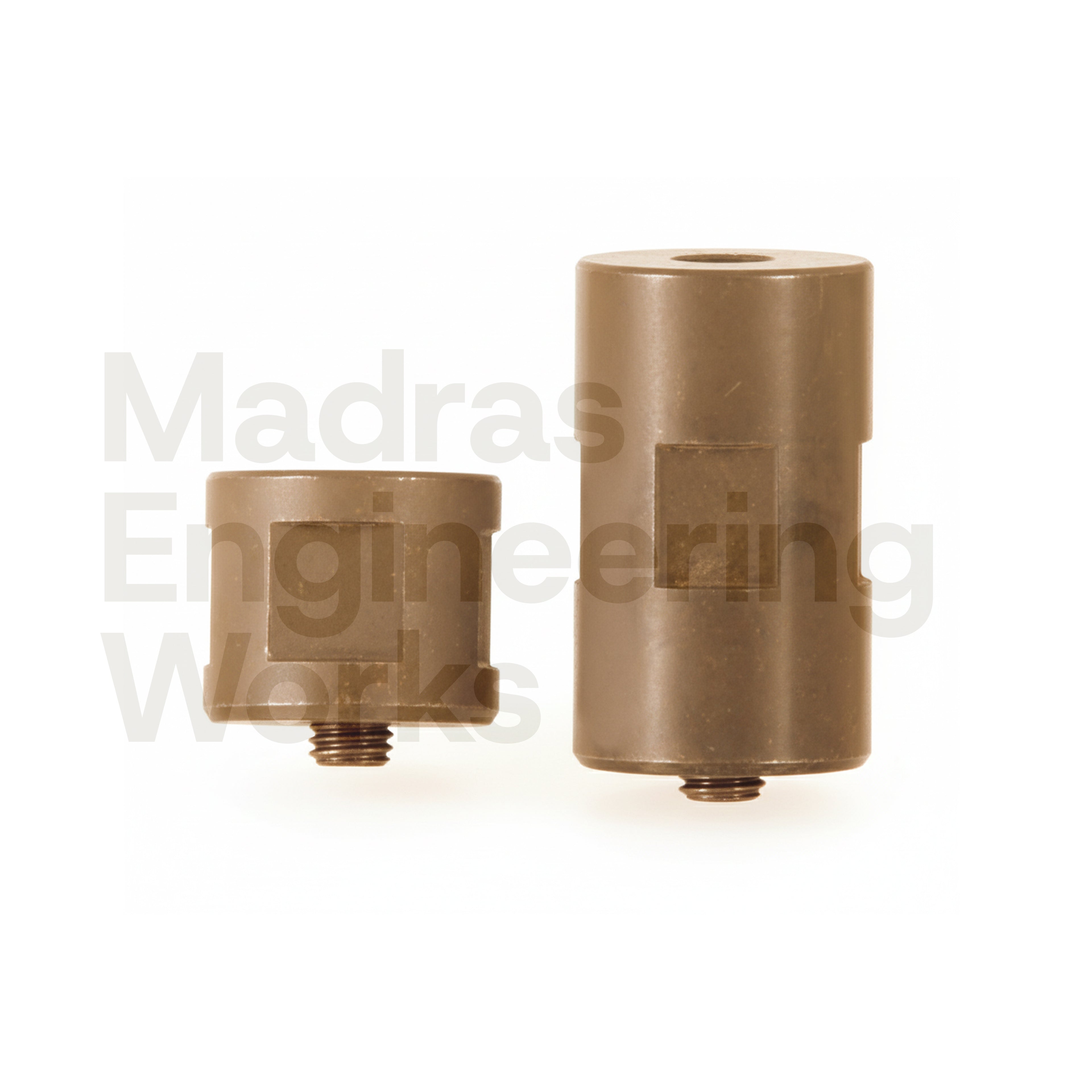
| Irregular casting, third-point contact | Self-Aligning Ball Element | T3-SBE-6 |
| Semi-finished blank with slight variation | Adjustable Support Bolt | T2-SB-1655 |
| Flat machined datum | Standard Step Block | T3-SB series |
Madras Engineering Works stocks all screw jack types and support elements for irregular workpiece clamping. Browse the screw jacks and workpiece support range. ISO 9001:2015 certified, Chennai stock.
Step 4: Select Clamps for Irregular Geometry
Once the workpiece is supported and located, you need to apply clamping force. The challenge with irregular parts is that the clamping points are often inaccessible to a standard strap clamp. Use the correct clamp type:
| Situation | Clamp Type | MEW SKU |
|---|---|---|
| Raised boss or wall blocks straight clamp access | Goose Neck Clamp | T1-GNC-11100 |
| Clamping point inside a recess or under a lip | Hook Clamp | T1-HK-1642 |
| Full top face must remain clear | Slot Clamp / Pinch Clamp | CES-SC-10 / PL-1A-12MM |
| Standard flat workpiece with variable edge distance | Slotted Strap Clamp | T1-SC-1175 |
| Heavy casting or die block, side hold | Thick Plate Clamp | CES-TPC-1/8 |
For a full guide to all clamp types and their applications, see the types of CNC clamps guide from Madras Engineering Works.
Step 5: Position Screw Jacks Correctly
Screw jack positioning errors are the most common cause of casting movement during machining. Follow these rules:
- Position jacks as far apart as possible to maximise the support triangle area. The triangle of support determines resistance to tipping.
- Use a swivel-head jack on rough or angled casting surfaces. A flat-head jack on an angled surface makes line contact — it will slip under cutting force. The swivel head self-aligns to match the surface angle.
- Lock the jack height with a lock nut before cutting. Machine vibration causes an unlocked jack to slowly creep, changing the support height during a long roughing operation.
- Never over-tighten the jack against the workpiece. The jack provides support — it is not a clamp. If you torque a jack hard against the workpiece, you distort the datum surface and introduce measurement error into every dimension referenced to that datum.
Browse Madras Engineering Works' full screw jacks range — ISO 9001:2015 certified, in stock Chennai.
Step 6: Clamping Sequence
- Position all screw jacks. Bring each into contact with the workpiece without applying load.
- Apply clamps loosely at all positions.
- Tighten primary clamps (closest to the primary datum) first — this seats the workpiece against the datum without distorting it.
- Tighten secondary and tertiary clamps.
- Lock all screw jack lock nuts.
- Verify the workpiece has not shifted using a dial indicator against a reference face.
- Only then run the program.
Common Mistakes When Clamping Irregular Parts
- Clamping directly on rough casting skin without a flat datum pad — the clamp tip bites into the uneven surface and the workpiece rocks under load
- Using a flat-head jack on a non-flat datum — it makes line or point contact, tips under cutting force, and changes the datum location mid-cut
- Over-constraining with more than 6 contact points — more than 6 contacts causes the workpiece to be over-located and may lift off one or more contact points when clamped
- Not locking screw jack heights — vibration causes creep in long roughing operations
Madras Engineering Works is ISO 9001:2015 certified and stocks all workholding components for complex irregular part clamping. To find the right components for your setup, use the Smart-Spec calculator or WhatsApp +91 95143 73702.
Frequently Asked Questions
How do you clamp irregular parts for CNC machining?
Clamp irregular parts using the 3-2-1 locating principle: three primary support points define the primary datum plane, two secondary points constrain a secondary face, one tertiary point prevents rotation. Use swivel-head screw jacks under irregular casting datum surfaces, self-aligning ball elements for third-point contact on rough surfaces, goose neck clamps to reach over raised bosses, and hook clamps for clamping points inside recesses. Madras Engineering Works supplies all required workholding components from stock in Chennai.
What clamps are used for castings and forgings on a VMC?
For castings and forgings on a VMC: use swivel-head screw jacks (CES-STSB-45) to support irregular datum surfaces, self-aligning ball elements (T3-SBE-6) as third-point supports, goose neck strap clamps (T1-GNC-11100) to reach around raised bosses, and hook clamps (T1-HK-1642) for clamping points inside recesses. All are ISO 9001:2015 certified products from Madras Engineering Works, stocked in Chennai.
How do you prevent a casting from rocking during CNC machining?
Prevent casting rock using 3-2-1 locating with swivel-head screw jacks. The primary datum plane (3 points) must be established on the casting’s most consistent reference surface — the three support points should form as large a triangle as possible. Use a self-aligning ball element as the third primary contact point. Lock all screw jack heights with lock nuts before starting the cut.
Where should screw jacks be positioned when clamping irregular parts?
Position screw jacks directly under the workpiece at the three primary datum contact points, as far apart as possible to maximise the support triangle area. The larger the triangle, the more stable the workpiece against tipping under cutting force. For casting datum surfaces that are not flat, use swivel-head screw jacks (CES-STSB-45) to match the surface angle automatically.
Can you use strap clamps on an irregular-shaped workpiece?
Yes, but the clamp must reach a flat clamping surface on the workpiece. Use goose neck clamps (T1-GNC-11100) to bridge over raised bosses. Use hook clamps (T1-HK-1642) when the clamping point is in a recess. Use slotted strap clamps (T1-SC-1175) where stud-to-edge distance varies. Never clamp directly on a rough or curved casting surface without a prepared flat pad.
Written by Husain, Founder of Madras Engineering Works — ISO 9001:2015 certified industrial supplier in Chennai. WhatsApp +91 95143 73702 or email enquiry@madrasengg.com.


0 comments